
Last updated on
21st March 2020

The Track

|
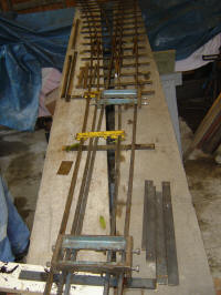
The 3½"and 5" gauge track is constructed of mild steel flat 3/4" x 3/8" (20mm x 10mm) on edge. Originally the rail was supported by bent 16swg mild steel chairs 1" wide, riveted into the rail with 3/16" soft iron rivets and either fastened to wooden sleepers by 1" x 12 mild steel counter-sunk screws. The sleepers were made out of any suitably treated wood although the majority are hardwood, and have a minimum dimension of 11" x 1 ¼" x 7/8". The sleeper spacing is every 10 to 13" depending on the location. Rails were joined using angle iron fishplates bolted to the rail. As and when sections of track have had to be renewed the rails have been welded to metal sleepers. The metal sleepers were often made by cutting up the old rail that was being replaced. Rail joints are now also welded. There are now only a few sections of track that are of the original construction. |
Track Foundations

|
Track foundations are concrete, to a minimum depth of 15" with a surface width of at least 12". A 4" soil pipe is buried alongside the track to convey cables and air lines around the site. The wooden sleepers of the track rest directly on the concrete. Where steel sleepers are used, these will normally rest on an unattached wooden sleeper below. This gives sufficient clearance below the rail for the concrete foundations to be covered by granite chippings to give a prototypical appearance. As with the track itself there has been a significant change from the original method of construction. Originally bricks were let into the ground at regular intervals and the sleepers rested on these. This quickly gave rise to problems maintaining accurate track levels and so work to place the original main line on concrete foundations was undertaken in the 1970s. All subsequent extensions were built with concrete foundations from the outset. |
Track Geometry
The minimum curve radius is 29ft in the steaming bay loop and 37 ft on the main line. There is an 18 ft transitional curve length on the outer main for a straight to a curve. The super-elevation design speed on the outer main is 6 mph (10 kph) with a maximum cant of 3.6° on the curve, cant being at a rate of 0.2° per ft. The concrete track sections were levelled to the appropriate track cant when laid in the late 1970s. The cant effect was not found noticeable so when the inner main was laid in the 1990s super-elevation was not used. The 3½" and 5" gauge tracks have a common outer rail and a minimum structure gauge of 3ft wide by 4ft 6ins high.
Points
|
The original points on the railway were of the stub type, where a whole section of track slid sideways to line up with the other track. These have now all been replaced by points of more conventional design and the points are now of all welded construction. The majority are operated by compressed air, but two, giving access to sidings, are operated by hand as required. |